The Jawbone Branch is coming along nicely to the point where I'm starting to look at how the engine roster is coming along. The SP 3203, SP 3237 and SP 3266 were photographed on the Jawbone, along with couple of shots with SP 3201 and SP 3227 taken on the Jawbone. The SP 3266 was the only larger 63" driver Mk-6 class engine allowed east of Inyokern on the Jawbone Branch. ALCo RSD-5s were also used for a short time in 1953 before they were fitted with the large spark arrestor stacks and the went back to the branch again after the end of steam in 1954 until the SD9s took over in the later 1950s, which pushes out of my modeling era.
Modeled Engine Roster
 |
| SP 3237 & 3266 at Searles Station - 5-30-52 - Carl Blaubach photo - Brian Black Collection |
Currently, I'm aiming to build SP 3203 and 3266. The SP 3203 still needs a custom built tender, which I still need to do major work on, so it's on hold for now. In this post I'm going to show the start of my work on a Balboa Mk-5/6 that I was able to pick up from a friend for $75 a few years back. The engine has some fairly severe wear on the driver plating, the rods screws are a bit wallowed out, The brake shoes and rigging are missing, and there's a couple of broken solder joints at the rear of the engine's frame which will need to be fixed in Part 2. I'll be retouching the cab sides and redecalling as the common factory 3244 decals were still applied.
I'll be rebuilding this model as SP 3266 for my Jawbone Branch layout. I've already covered part of the work on another SP 3266 that I painted, decaled, weathered, and converted to use an Athearn-Genesis 120-C-6 tender for a customer for use at LMRC several years ago. This Balboa model will be a similar conversion. The conversion to the both-rail-pickups on the Athearn-Genesis 120-C-6 tender will help offset the pickup issues with the failed plating on the drivers.
The Frame Damage
 |
| Right side view of the cracked frame solder joints. |
It appears that at some point in the past, the solder joints between the rear sideframes and the cab-wall bulkhead/drawbar screw mount plate broke loose and allowed the engine to hog-sag pretty badly. This is the first step I made in repairing and getting this engine back into service.
 |
| Left side of the cracked solder joints along the rear frame. |
The analog wiring is a bit of mess and somewhat in the way of doing the work with the resistance soldering unit, so I removed most of it for now.
Soldering the Frame
The repairs were done in two steps with a resistance soldering unit. One probe was placed inside the drawbar hole, and the other side contacted on the outer side of the frame, squeezing them two parts together while solder was flowed in.
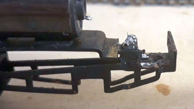
Fixed frame with a little extra solder that I still need to clean up. The frame pickup point on the back of the motor mount needs to be touched up as well (previous owner left a wad of solder on there).
In Closing
Once the frame was fixed, I hooked up clip leads to power the motor and test run the drive. Not surprisingly the drive is actually fairly smooth. This is common on engines which show signs of wear on the drivers to this level... they've already run a number of miles, and should still be fairly good unless they're completely worn out. So aside from the lack of plating on the drivers, this drive still is in mid-age, with a number of miles still able to be run.
In future posts on this project, I'll be going through the conversion and setting it up to be more historically accurate for service on the Jawbone. Eventually, I plan to equip it with DCC and sound as I get close to finishing it for service.
Jason Hill
Related Articles:
New Drawbar Mount for Athearn-Genesis 120-C-6 Tender - Fitting for SP 3266 (First)
Modeling SP Road Switchers (Part 2) - Medium Steam Engines - Including Mikados


No comments:
Post a Comment